

Mechanical fasteners
How to account for fastening your insulation to your structure

If you’re like me and enjoy getting lost in the theoretical side of Passivhaus you will probably join me in having completely disregarded how to actually build my design at some point. I’m quite happy specifying 300mm of insulation but forget that it doesn’t just float in mid-air and has different connections to and through it. This oversight can often lead to a more liberal estimate of heat loss that can prove costly when it gets down to it at the end of a project.

Understanding how your design will actually get built is a vital component to being a good Passivhaus designer. The thermal impact of the smallest of thermal bridges, if they occur in any great quantity, can be large enough to swing a project from passing the Passivhaus standard to failing it in one fell swoop.
Little bits of metal that puncture through the insulation layer are ones to watch out for. Although the heat loss through an individual connection may be small, when you have hundreds of these across an assembly it can soon add up.
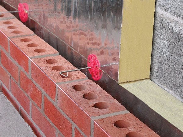
If you’re aware of them at an early stage you can make sure they’re specified in a low thermal conductivity material in the architectural specification. But forget about them and turn up on site to find the metal fixings puncturing the insulation line, suddenly you can find yourself in a bit of a panic.

An unbroken insulation layer is the Passivhaus designers dream but you’ll need some way to hold that layer in place and some way to hold the exterior and the interior of the façade together. Brick ties, insulation fixings and roof fasteners are all classic examples of mechanical fasteners.
Unfortunately they do create small thermal bridges that repeat across a construction build up, often around 4 to 9 of them per m². So instead of trying to calculate the total number of fasteners across the building, PHPP uses a U-value supplement method which gives you an additional W/m².K to add to your assembly (an additional energy loss per m² per Kelvin)
Let’s dig into how to model them using the calculator within PHPP.

Mechanical fasteners are not going to break the bank when it comes to heat loss, but if you’re tight up against it you’ll regret not having an allowance for them.
In the concept stage of a project you can definitely get away with ignoring them, most likely your project architect won’t have worked out the finer details around fixings. Once you get into the technical design it’s well worth making sure you have a placeholder and it’s your responsibility to start the dialogue with the project team.
Asking questions around which materials are being specified for fasteners a bit too early is better than too late. Once you have a set of section drawings for the assemblies through from your architect it’s probably a good time to start considering them.
You won’t be able to model the fasteners properly until you have the assemblies completed but it’s worth looking out for and being aware of any fasteners when you go though modelling them. Adding a placeholder value to remind you is a great way to keep on top of it.
In some cases it won’t be until stage 5 that you have a sub-contractor design though to get the exact specification and density of fixings. Until then conservative assumptions are the way to go. But you need to make sure that you’re guiding the design team through to a good thermal solution, so push for low conductivity options wherever you can spot them.
This can be as simple as replacing aluminium fixings with stainless steel ones in the architectural specification. Just this small change reduces the U-value supplement by 90%.
If you’ve managed the design process well, there’s nothing huge to worry about but suddenly finding a high density of aluminium fasteners can lead to a considerable jump in space heating demand or heating load. Fasteners affect the space heating (or cooling) demand more than the heating load target. In a worst case scenario you could see a 30% increase in the space heating demand and a 15% increase in heating load.
Adding some conservative assumptions at the start of technical design will save you from this nasty shock.

PHPP has an in-built mechanical fasteners calculation tool. I would recommend using this to track any fasteners penetrating the insulation throughout the design process.
It’s not the easiest thing to find as you will need to open one of the groups, Mechanical fasteners in this case, at the top of the U-values worksheet. I personally like to keep any groups I’m not using hidden and any I am using visible; it can really help keep track of everything.
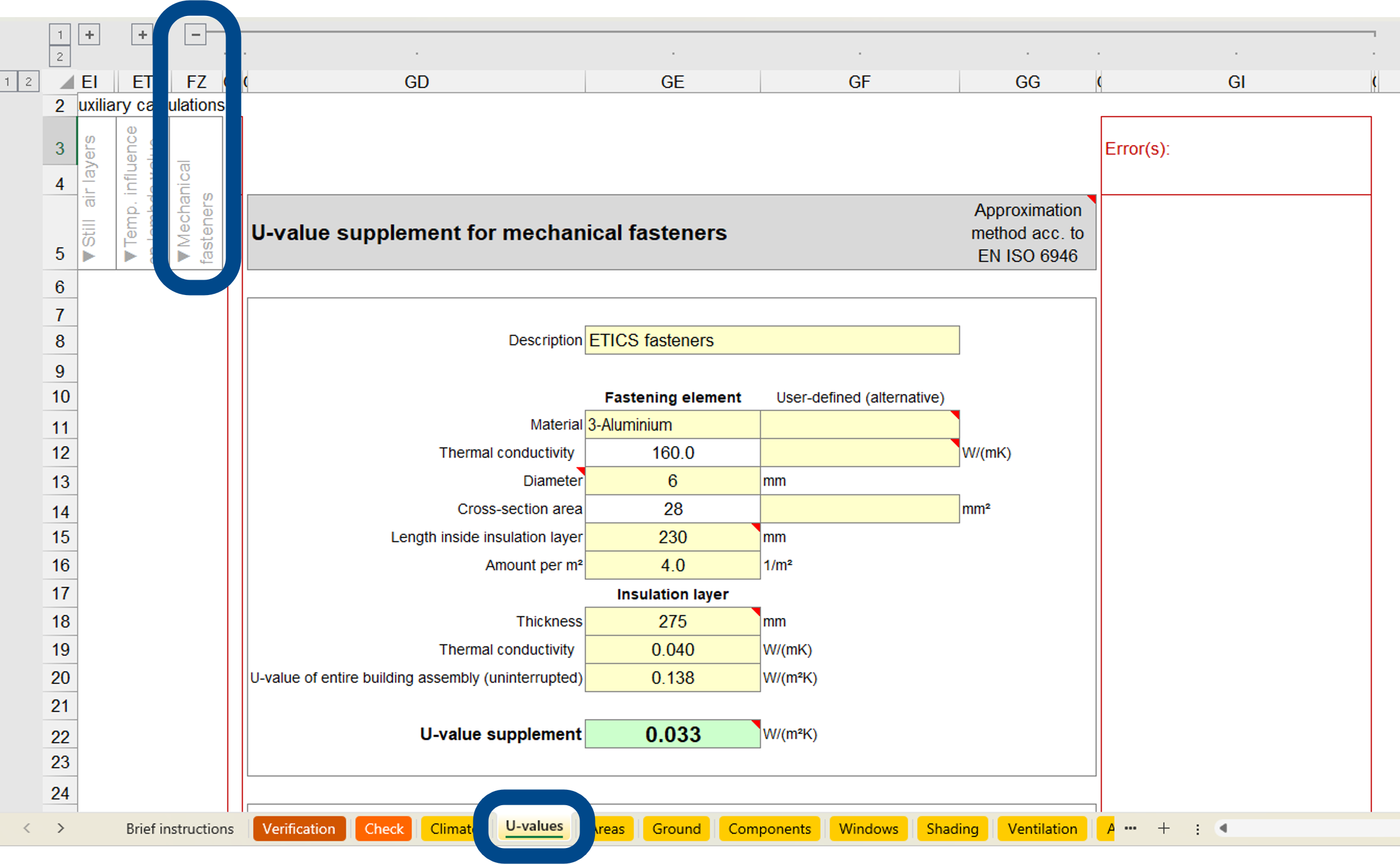
Once you unhide the group, you should see this (or a blank version at least):
This tool isn’t for everything. It’s based on the approximation method outlined in EN ISO 9649 that defines methods for calculating the thermal resistance and transmittance of different building components and building elements. As such, there are a few cases in which this calculation is not an accurate way to model your fastener.
It should not be used for:
Losses for fixings through an air layer, this is for insulation layers only
Low thermal conductivity fasteners where the conductivity is <1 W/m.K
In cases where the both ends of the metallic part of the fastener connect to metal - this creates a more complex 3D heat loss problem
Note there are low conductivity fasteners on the market that are made from low conductivity material. These can often get ignored as they will not affect the heat loss to any noticeable extent. Ancon’s Teplo range made from basalt fibre is a great example. With a thermal conductivity of just 0.7 W/m.K you can save yourself the trouble of having to model them.
It is intended for penetrations of insulation layers by mechanical fixing elements such as:
Wall anchors in double wall masonry
Roof fasteners
Fasteners in composite panel systems
So, presuming you have one of these you’ll need to know some key thermal and geometric information:
Material: In the first few cells you can select the material of the fastener from the dropdown (this will give you a default thermal conductivity) or you can provide your own data.
Diameter or cross-sectional area: In the second section you will need to enter the cross-sectional area of the fastener. You can enter the diameter for circular fixings (most fasteners are) or for different geometries you can calculate the cross-sectional area and enter it in.
Length inside the insulation layer: This is an interesting one, the length inside the insulation layer isn’t necessarily the length of the fastener on a datasheet. You’ll need to work out how much of the fastener is in the insulation layer once fitted.
It’s also worth noting that for fixings that are installed at an angle, this length can be greater than the thickness of the insulation layer.
Amount per m2: The density of fasteners (number per m²) accounts for how often this thermal bridge will occur over the assembly. This can vary in the region of 4 to 9 per m².
Insulation layer properties: The thickness and thermal conductivity of the insulation is needed alongside the overall U-value of the assembly. This can be found in the assembly U-value calculations you’ll already have completed (another article on this to follow). It’s worth noting that you’ll need to do a new fastener calculation for every type of assembly that has fasteners. However, I wouldn’t worry too much about this until you have an accurate design, just a placeholder will suffice through design.
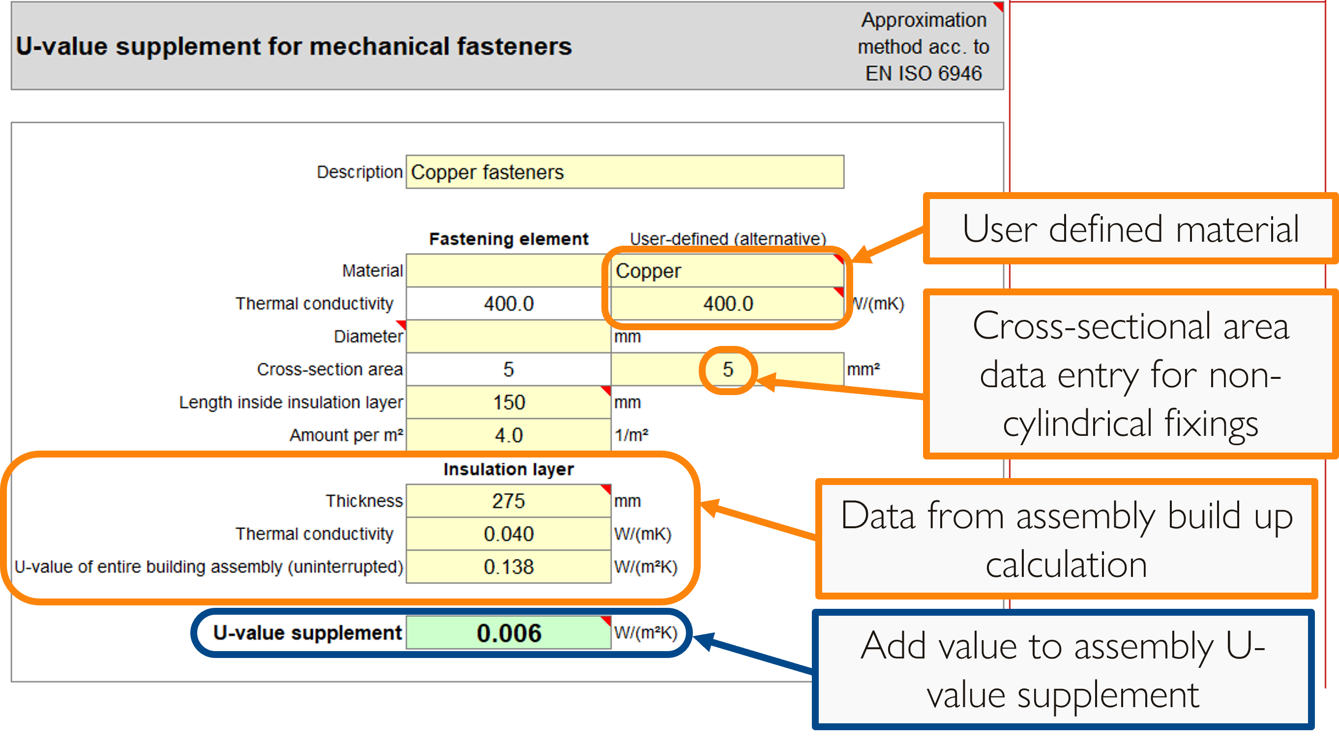
The example above shows an example of using the user defined fields.

Once you’ve used the mechanical fasteners calculator to work out your U-value supplement you will need to add it to the relevant assembly.
This is also entered in the U-values worksheet, under the specific assembly the fasteners are going through, in the U-value supplement cell, typically in column R.
If you already have another U-value supplement value in here related to a different repeating thermal bridge, make sure you add your calculated value onto this. If the mechanical fasteners are close to another element that is also causing thermal bridging you might need to consider the 3D heat loss effects, but you can always ask your certifier how to proceed in such circumstances.

Now you know how to model mechanical fasteners that penetrate the insulation layer
WHY: Mechanic fasteners can easily be forgotten but still add to the heat loss
WHEN: Add an allowance at early technical design but replace with a more detailed calculation pre final certification
HOW: Using the ‘Mechanical fasteners’ calculation tool in the U-values worksheet of PHPP
WHERE: Add the output of this calculation into the ‘U-value supplement’ field in the relevant assembly in the U-values worksheet

Passivhaus Preceptorship bridges the gap between qualification and practice, by guiding and mentoring you through your first Passivhaus projects. If you find this content valuable please help spread the word by sharing.

Keep up to date with all our latest posts by subscribing and have a peruse of all the posts in our archive: